Answer
Dec 22, 2025 - 08:30 AM
Adjustment Procedure
The adjustment mechanism for Brand Hydraulics valves is generally similar across models. The exact tools and location may vary slightly, but the principle is the same.
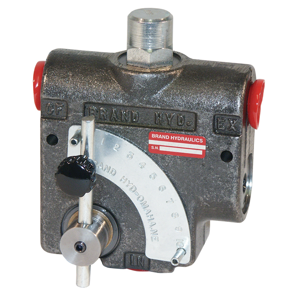
- Locate the Adjustment Mechanism: Find the adjustment point on the valve body. This is typically a set xxxx concealed by an acorn nut or a protective cap to prevent tampering.
- Remove Protective Cap/Nut:
- For flow adjustment, you may need to remove a red rubber guard or an acorn nut.
- For relief pressure adjustment (if equipped), you will likely need to remove a larger acorn nut.
- Loosen the Locknut: A jam nut (locknut) secures the setting. Loosen this nut with a wrench to allow the adjustment xxxx to turn.
- Adjust the Setting: Use a screwdriver or an Allen wrench (hex key) to turn the inner adjustment xxxx .
- Clockwise rotation typically increases the pressure or decreases the flow (making the orifice smaller).
- Counter-clockwise rotation typically decreases the pressure or increases the flow.
- Make Incremental Changes: Turn the xxxx in small increments (e.g., 1/8 turn at a time). Large adjustments can cause significant changes in performance.
- Test the System:
- Start the engine and operate the hydraulic system to its normal operating temperature (typically 100-140°F).
- Use a pressure gauge or flow meter to accurately measure the results of your adjustment.
- Repeat steps 4-6 until the desired performance is achieved.
- Secure the Setting: Once the desired setting is reached, hold the adjustment xxxx in place and tighten the locknut securely against the valve body to prevent the setting from changing during operation.